Export Project
Once your project is completed, validated, and saved to the server, you can export it. This produces files in the formats expected by the PCB manufacturer (JLCPCB in this case). Specifically, there are two main types:
- Gerber: serves as a blueprint for the PCB, providing information on the shape and position of copper traces, silkscreen, and solder mask.
- NC Drill: provides information about the holes in the PCB, including location, size, depth, plating, and more.
Gerber Files
-
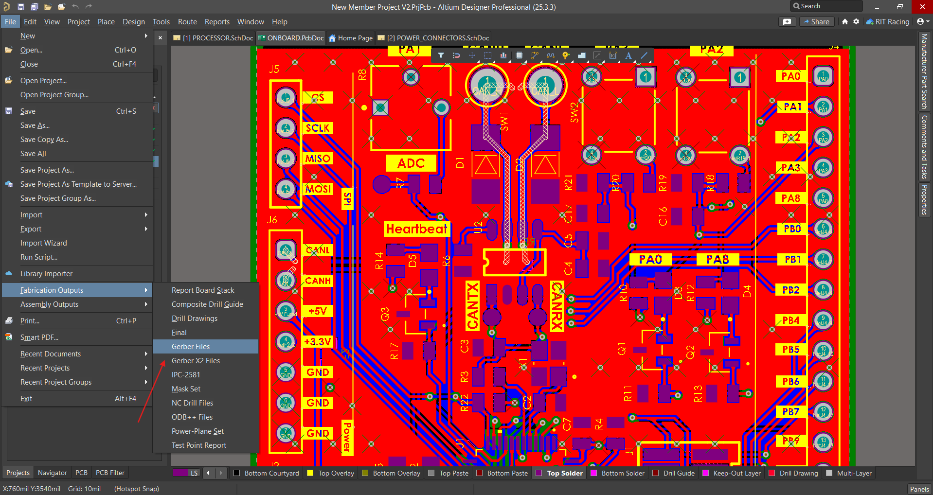
Ensure you are in the PCB document in your project.
-
Navigate to File → Fabrication Outputs → Gerber Files.
-
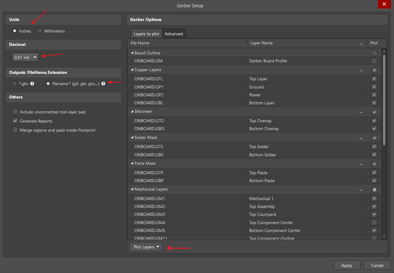
In the window that opens, ensure the parameters are as follows:
- Units: Inches
- Decimal: 0.01 (this defines the coordinate precision)
-
In Plot Layers (at the bottom) choose Select All to ensure that every layer is included in the export.
-
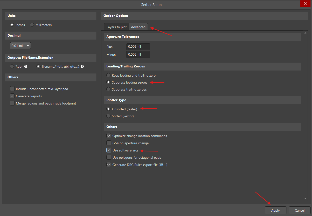
Switch to the Advanced Settings tab at the top and ensure the parameters are set as follows:
- Leading/Trailing Zeroes: Suppress leading zeroes (reduces file size).
- Plotter Type: Unsorted (faster).
- Others: Use software arcs.
-
Once all settings are verified, select Apply.
-
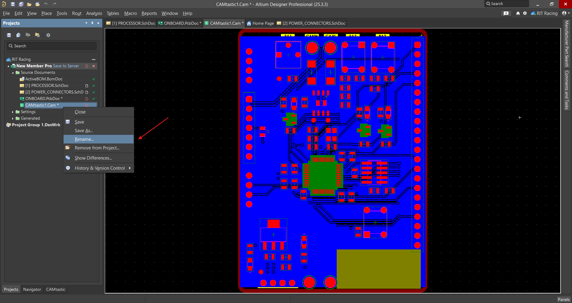
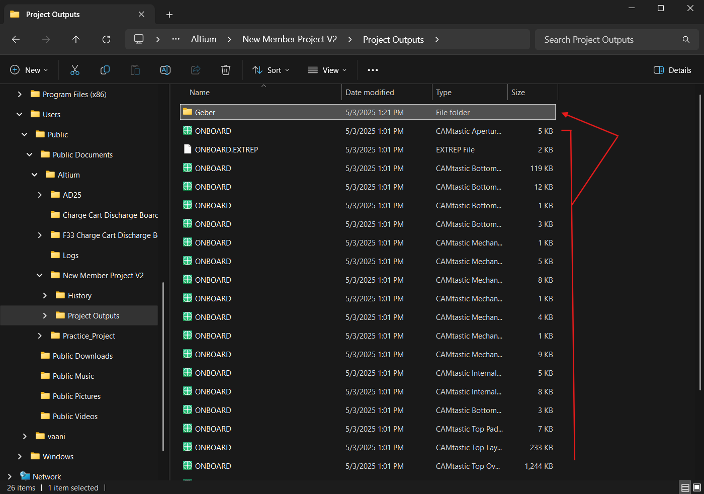
The generated CAMTastic file will open. Rename this file to "Gerber".
-
Navigate to the generated output files on your system. This path should be Users → Public → Public Documents → Altium → Your project → Project Outputs. Inside this folder, create a new folder named "Gerber". Move all the files into this folder.
That's the Gerber export complete.
NC Drill Files
-
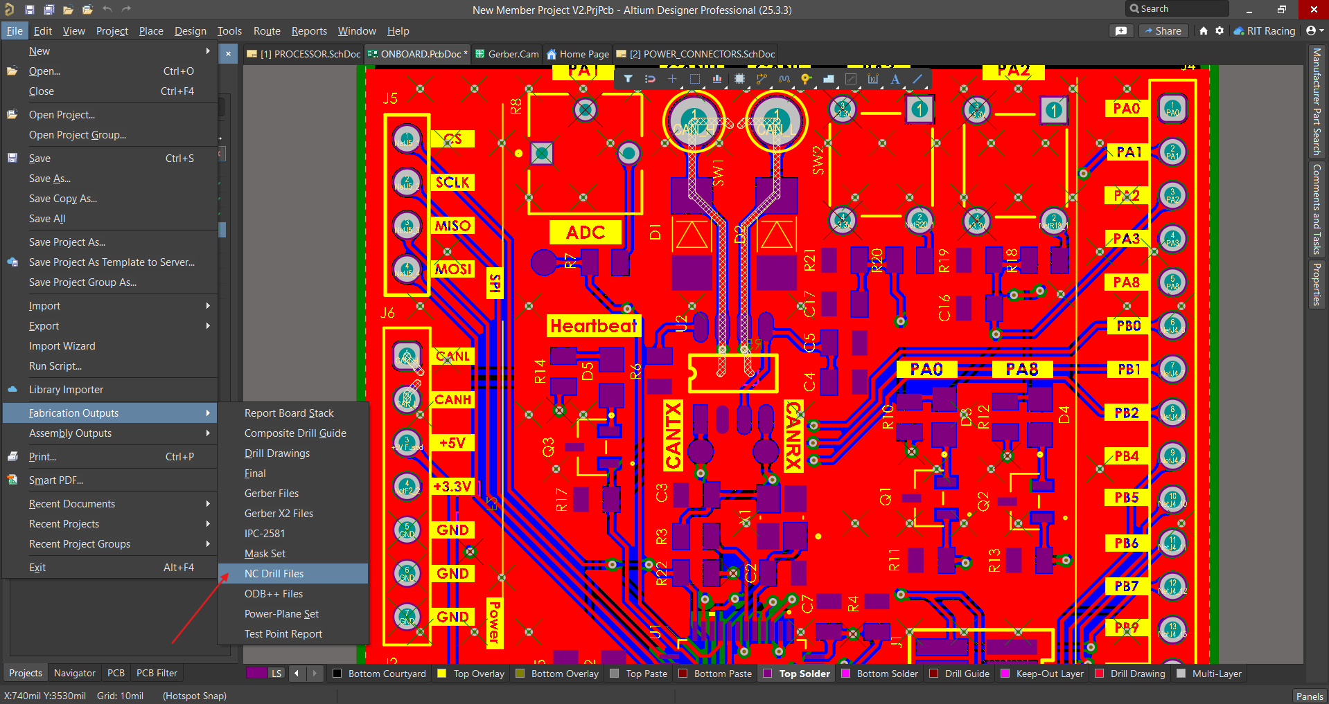
Return to the PCB document in Altium and navigate to File → Fabrication Outputs → NC Drill Files.
-
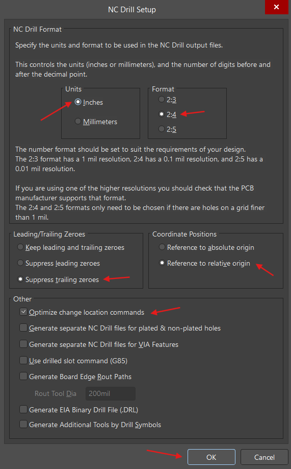
In the setup window that pops up, ensure the following parameters are selected:
- Units: Inches
- Format: 2:4
- Leading/Trailing Zeroes: Suppress trailing zeroes
- Coordinate Positions: Reference to relative origin
- Other: Optimize change location commands
-
Select OK.
-
The Import Drill Data window will pop up. Select OK here as well.
-
As before, a generated CAMtastic file will open. Rename this file to "Drill".
-
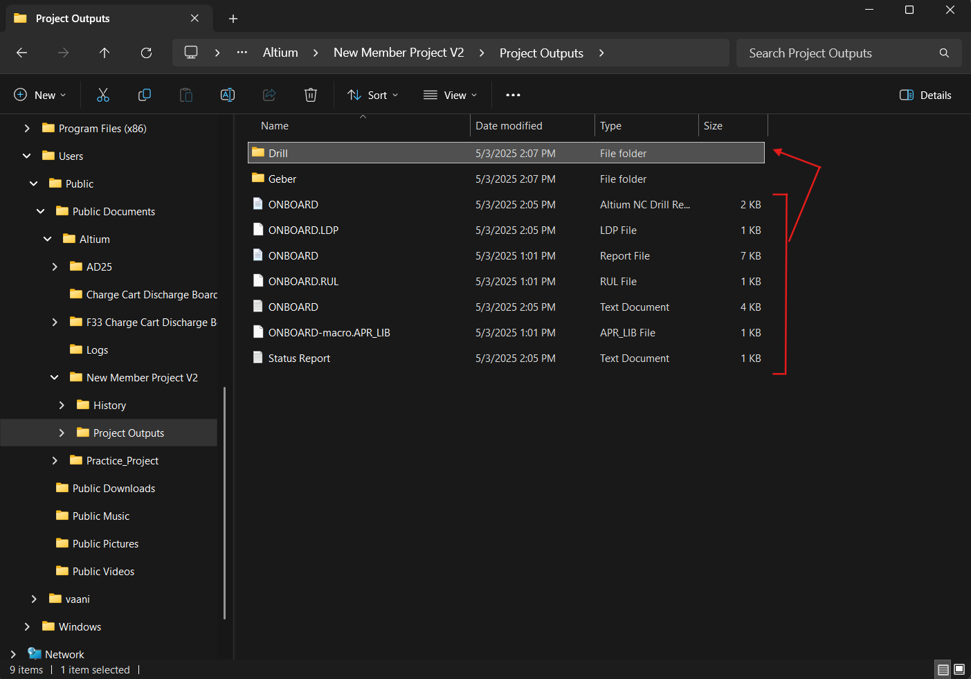
Navigate to the same Project Outputs folder in your file system (Users → Public → Public Documents → Altium → Your project → Project Outputs).
-
Create a new folder named "Drill" and place all the new files there.
File Compression
-
Create a third folder in the same Project Outputs directory (Users → Public → Public Documents → Altium → Your project → Project Outputs) named the same as the title of your project on Altium.
-
Move the Gerber and Drill folders into this new folder. Compress this folder. (On Windows: right-click and select Compress to → ZIP file.)
This ZIP file is your final output which can be sent by the Electronics Lead to JLCPCB for manufacturing.